Synchronization of data
If the same geometric figures are present in East and West, then the cutting wire is running parallel to the y-axis and there are no problems. On both sides of the wire, there are always points that correspond exactly to each other, so they belong together. The situation is different when the east and west sides have two different figures. The cutting process inevitably leads to a skewed wire (conical cutting in Figure 1).
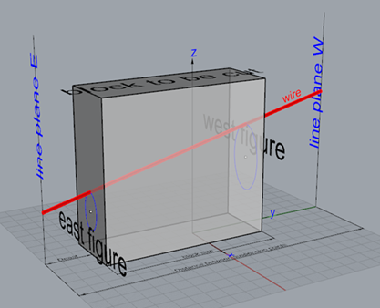
Fig. 1 Tapered cutting: East and West side have different geometric figures
By now, you have to worry about the points assignment on both sides, i.e. the problem of data synchronization occurs only when creating tapered cuts.
Figure 2 shows both profiles of the heavily swept wing (red = root, blue = tip). After moving these two figures apart on a wingspan (tapered cutting), a modified data set is obtained (see Fig. 3). The red (East) and blue (West) point distributions describe the curves of the two bow suspension points to create a wing with the required span and profiles at the root and at the tip.
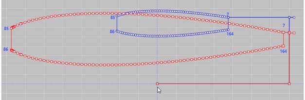
Fig. 2 Profiles (red = root, blue = tip) of a heavily swept wing with cutting paths (Departure and access)
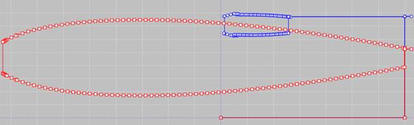
Fig. 3 Both of the bow suspension points must run on the respective curves to produce the required wing. The dataset is a result of the Tapered Cutting transformation.

Fig. 4 Enlarged area of the upper blue curve of Fig. 3 from point 7 on
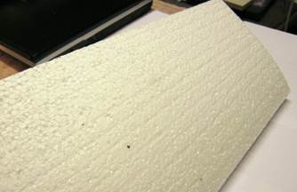
In picture 4, an enlarged part of picture 3 is shown, i.e. the wire moves alternately forward and backward at the western suspension point, it causes a scoring as you can see in Figure 5. This would make the wing useless. The reason behind this cutting result is the non-synchronized data set. The same dataset, but synchronized, leads to the result shown in figure 6 – as expected.
|
Fig.5 Unsynchronized data set |
Fig.6 Synchronized data set |

What does synchronizing actually mean?
Geometric figures are represented in CNC by point distributions. The wire connects e.g. the i-th point of the east side with the i-th point of the west side. Then it moves to the (i + 1) -th points and both are connected. These connections in succession create an area in space (our cutting surface in the foam). Generally different lengths must be traversed during the cutting time available for the conical cutting on the east and west sides. The result is that the shorter side has to wait for the longer one. Waiting means pausing for some while at one place, and that means, unlike milling, greater burnup, which in turn creates a hole in the material. To avoid this, the points must be assigned to each other, so that the points are adequately traveled without one side having to wait for the other one or to drive back.
Who is responsible for the synchronization?
Synchronization means point assignment between the two point distributions of the east and west side. This assignment can be done in an infinite variety of ways. However, there is only one useful, and this is determined by the designer in the CAD program, e.g. he wants to streamline the wing construction. Therefore, the point assignment includes constructor knowledge. Not all CAD programs can take this knowledge into account when saving the point distribution. Even worse is when East and West figures are generated completely independently. When the program ICE reads in and runs these records, you get everything else, but not the desired streamlined wing construction, i. e. the geometry created has little in common with the intended one. How should ICE know this? For ICE there are only point distributions, nothing more. Actually, the CAD program is responsible for this, because e.g. a streamlined wing construction is part of the construction; the point distribution knows nothing about it afterwards.
Is it possible to check the synchronization of a data record?
It’s possible with ICE.
What can ICE do?
· The most convenient solution is the following: The data record is e.g. in a CAD program generated in a synchronized way and ICE is enthusiastic.
· Subsequent synchronization
A subsequent synchronization is mathematically very complex and can only be of a speculative nature. You have to assign the geometries that are relevant, i.e. without the areas of the departure and access routes. My method is an approximation method for the assignment of the point distributions in East and West. But if the design program may have added other correlations, I cannot do anything. It may work, but the opposite is also possible!
How can you achieve the best results?
One has to tell ICE which data areas should be correlated. In the mentioned example above, you instruct ICE using the group editor that the top surface of the profile (data points first point = 7, last point = 85) should be synchronized and in a second run the underside (data points 86-164). By doing so, you get the excellent result shown in Figure 6 above. But keep in mind: it is a speculative approximation. The original constructor's knowledge is gone, and ICE naturally has no idea about it.
Conclusion
The function synchronize is only used for tapered cutting, there it is essential. To create conical sections, the cutting data of the East or West figures (which are to be created on the east or west side of the block) must be assigned (synchronized). Only then, it must be considered how to position the styrofoam block on the cutting table. With these dimensions, the data are transformed by means of the Tapered cutting function to the respective suspension points of the bow. Only now the cutting procedure can be started. For successful cutting, one has to pay attention to the order of the steps to be performed.
Therefore, the order of action is as the following:
First of all, synchronizing then positioning and then perform Tapered cutting.
Can you automate this process?
Barely. You have to know what you are doing right now!
Author: H. Iwe
Written: December 2018
Last modification: December 2019