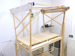
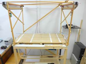
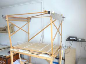
Theoretical fundamentals of the CNC hot wire winch cutting machine
|
|
|
|
|
|
|
Geometry:
|
|
Mathematical Basics
Stepper motor
The
smallest unit of a stepper motor movement consists of a rotation by an angle ![]() that emerges from the data sheet. Typically this is
that emerges from the data sheet. Typically this is
![]() (e.g. the value of the motor Vexta PXB44H-02AA-C8
we use), which means that the motor requires
(e.g. the value of the motor Vexta PXB44H-02AA-C8
we use), which means that the motor requires ![]() steps for a full turn. If a thread on its axis with an
effective diameter d is wound or unwound, it generates the smallest possible
variation in length
steps for a full turn. If a thread on its axis with an
effective diameter d is wound or unwound, it generates the smallest possible
variation in length ![]() . The size
. The size ![]() is called the step density in [steps/mm]. Both sizes depend on the
diameter d and need to be measured. It is irrelevant whether you measure d
or
is called the step density in [steps/mm]. Both sizes depend on the
diameter d and need to be measured. It is irrelevant whether you measure d
or ![]() . Using d= 6.5 mm results in the typical orders of magnitude of
. Using d= 6.5 mm results in the typical orders of magnitude of ![]() or
or ![]() .
.
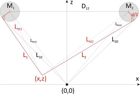
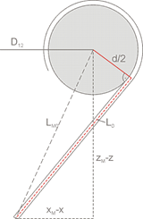
Geometry of the construction
|
Initial rope length: L10, L20 |
motor shaft diameter D |
|
step density in steps/mm: md |
rope diameter d0 |
|
smallest
variation in length: |
effective diameter d=D+d0 |
Taking all measurements in relation to the motor shaft center, one can calculate the tangential lengths. For practical purposes this procedure is simpler. In calculations we refer always to tangential cable lengths and for convenience these are simply denoted by L. The lengths to the shaft center play a role only as auxiliary variables in calculations, beside this they are meaningless.
|
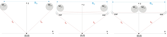
Motor M1: (xM1, zM1= zM2) Motor M2: ( xM2, zM2) |
Distance M1M2: D12 |
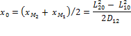
Center deviation: x0 |
||
|
D12 = xM2 + |xM1| = xM2 - xM1 |
|
|||
|
|
|
|
|
|
|
|
|
|||
![]()
![]()
![]()
![]() -
-![]()
![]()
![]() +
+ ![]()
![]()
![]() -
-![]()
![]()
![]()
![]()
A
symmetrical construction ![]() , i.e. the center deviation goes to zero.
, i.e. the center deviation goes to zero.
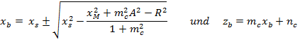
Coordinate transformation
![]()
![]() and with
and with ![]()
![]()
![]() and with
and with ![]()
![]()
![]()
![]()
![]()
Transformations:
|
|
|
|
|
|
|
|
|
Properties of the coordinate transformation
Origin:
The origin is given by ![]()
![]() , and if
, and if ![]()
As a result of the following considerations the resolution of the cutter can be determined in x as well as in z direction.
Parallel translation in z direction:
Infinitesimal changes of the function z(L1,
L2) result in![]() . A small parallel shift in z-direction is characterized by dL1 =
dL2 = dL. Some elementary manipulations lead to
. A small parallel shift in z-direction is characterized by dL1 =
dL2 = dL. Some elementary manipulations lead to
![]()
The largest changes occur at x=0 and L1 = L2 = L:
![]()
Taking into account finite changes in length of the
rope ΔL (ΔL <0 for reductions, >0 for extensions)
a resolution is obtained in z direction of ![]() .
.
The change in length ΔL depends on the step density md of a stepper motor in the following way:
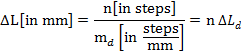
One motor step (![]() ) at z = 0 provides
) at z = 0 provides
![]() .
.
This resolution degrades with increasing z and amounts
at z = 100mm to the value of Δz
= 0.134mm. Thereby the x coordinate is changed by ![]() , i.e. it normally does not remain constant during
shifts in z direction.
, i.e. it normally does not remain constant during
shifts in z direction.
Parallel shift in x direction:
A parallel shift in x direction arises from changes in rope length of the type
![]() .
.
From elementary manipulations follows
![]()
One motor step (![]() ) results in a resolution of
) results in a resolution of
![]()
The worst resolution is received at z = 0 (if the sum ![]() is the largest), namely
is the largest), namely![]() . A numerical value originates from typical
parameters of constructions realized:
. A numerical value originates from typical
parameters of constructions realized: ![]() You see, not only the stepper with about 0.1 mm per
step, but also the geometry of the machine delivers its share to a total
resolution of about 0.2mm. Can we improve the overall resolution by an ingenious choice of the
geometry? Unfortunately, this is not possible because both resolutions depend on
the ratio 2L/D in almost the same way.
You see, not only the stepper with about 0.1 mm per
step, but also the geometry of the machine delivers its share to a total
resolution of about 0.2mm. Can we improve the overall resolution by an ingenious choice of the
geometry? Unfortunately, this is not possible because both resolutions depend on
the ratio 2L/D in almost the same way.
Working area of the cutter
|
|
M : (xM, zM) Mt: (xt, zt) Pi : (xi, zi)
|
|
|
|
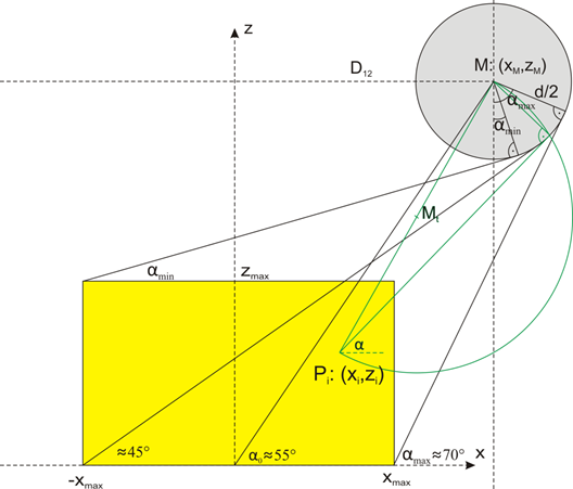
Circle
of motor shaft k around M: ![]()
Thales
- circle kt around Mt: ![]()
Chordale c =
k - kt: ![]()
![]()
Using chordale c and circle of motor shaft k we get the osculation point of the tangent:
![]()
![]()
During the cutting process the wire moves from point Pi to point Pi+1:
![]()
At the same time on the motor shaft a change in angle arises of
![]()
The
angle change corresponds to a radian of ![]() on the motor shaft.
on the motor shaft.
During winding (shortening of the rope) this amount Δb must be additionally achieved because the osculation point moves upwards, i.e. the finite geometry causes more winding. If you not do this the objects to be cut become too small. Vice versa this length is won back during unwinding (rope extension) which means someone has to unwind less. From these considerations, there is a real change in the rope length of
![]() with Δb<0 for UP and Δb>0 for DOWN.
with Δb<0 for UP and Δb>0 for DOWN.
On the basis of this formula it is very easy to estimate some points using (xM,zM)=(500,700).
|
|
xi |
zi |
|
Δb(d=6.4mm) |
|
αmax |
250 |
0 |
70° |
|
|
α0 |
0 |
0 |
55° |
|
|
α-max |
-250 |
0 |
45° |
|
|
αmin |
-250 |
250 |
30° |
|
|
αmax-α0 |
|
|
15° |
0.90mm |
|
α-max-α0 |
|
|
10° |
0.65mm |
|
αmin-α0 |
|
|
20° |
1.16mm |
The numerical values insistently
underline the
necessity to take into account the finite diameter of the motor shaft.
Space in which the cutting machine moves
The underlying space is not a Cartesian, i.e. the rule of Pythagoras is not valid here. This space is characterized by a kind of Manhattan-curvilinear geometry in which distances are defined by a Hamming measure.
Cutting speeds
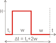 A motor can only wind or unwind the rope. One motor step is controlled by
an impulse cycle as shown in the figure. First of all the direction must be
transferred. After a waiting time of t0≈1ms the clock impulse is transferred and
holds for a time of w[in ms]. The signal must stay at low level for the same
time resulting in a total impulse cycle of the length Δt=t0+2w. If the motor is continuously
rotated without a change in direction (t0 is necessary to
change the rotating direction) we get for the change in length
A motor can only wind or unwind the rope. One motor step is controlled by
an impulse cycle as shown in the figure. First of all the direction must be
transferred. After a waiting time of t0≈1ms the clock impulse is transferred and
holds for a time of w[in ms]. The signal must stay at low level for the same
time resulting in a total impulse cycle of the length Δt=t0+2w. If the motor is continuously
rotated without a change in direction (t0 is necessary to
change the rotating direction) we get for the change in length ![]() during time Δt=2w the maximal possible radial rope velocity
during time Δt=2w the maximal possible radial rope velocity ![]() . If both motors pull, the cutting bow moves up.
. If both motors pull, the cutting bow moves up.
![]()
A
typical value of ![]() amounts to
amounts to ![]() Therefore the maximal possible radial rope velocity is calculated for w=1, 2, 20 sequentially
with 50, 25, 2.5mm/sec.
Therefore the maximal possible radial rope velocity is calculated for w=1, 2, 20 sequentially
with 50, 25, 2.5mm/sec.
In
z direction we get due to geometry only the effective part ![]() , in x direction
, in x direction ![]() , i.e. the velocity in z direction exceeds
the horizontal one by
, i.e. the velocity in z direction exceeds
the horizontal one by ![]() that means it is 1.5 times higher (for D12=1000mm,
L=900mm).
that means it is 1.5 times higher (for D12=1000mm,
L=900mm).
In practice this implies using times
of w=2, 20 the horizontal velocities of 14 and 1.4 mm/sec respectively are
reached, however vertical velocities of 21 and 2.1mm/sec respectively. These
considerations imply that the time w=2 is only suited for quick arrivals or
departures. For the cutting process itself an optimum must be found that
certainly is of the order of w≈10 that means is equivalent to![]() . If you want to cut for some reasons or
considerations with a special horizontal velocity of
. If you want to cut for some reasons or
considerations with a special horizontal velocity of ![]() [in mm/sec] the corresponding w can be estimated using
the simple relation
[in mm/sec] the corresponding w can be estimated using
the simple relation
![]()
Now what does the term optimum mean? The cutting process depends on many parameters which are integratively summarized in the value w chosen for every point individually. More you cannot make, but this is already difficult enough. Ultimately, the most important role plays experience.
The hot wire generates a burning lane of a definite width. Using chrome-nickel-wire of diameter 0.5mm we can expect a burning lane of approximately 1mm thickness, i.e. around the object to be cut a cutting lane with a virtual milling cutter of approximately Ø1mm diameter must be generated (e.g. with the program BOcnc). During the cutting process this thickness is influenced by the material to be cut, by the curvature radius of the cutting lane etc. After all you have to make test cuts to find suitable parameters.
Influence of changes in rope thickness
During the cutting process the rope is wound and unwound many times with a relatively small radius. The originally round rope changes in the course of time to a more oval shape, i.e. it suffers a flattening.
|
|
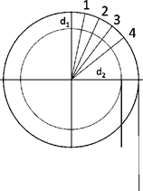
1, 2, 3 ... motor steps
md ... step density in steps/mm
D .. motor shaft diameter
d0 .... rope diameter
d=D+d0.. effective diameter
A
full rotation has N steps. Thereby the rolling circumference![]() and
and ![]() respectively are unwound.
respectively are unwound.
![]()
![]()
![]()
![]()
![]() ,
, ![]() with x as change in rope thickness.
with x as change in rope thickness.
![]()
From
this a difference in rope length of ![]() follows due to a change in diameter
follows due to a change in diameter
![]()
Typical values: D = 6mm, d10=0.4mm (dyneema fishing line)
A flatness of 0.1mm leads to 1.5% change in length that means a rope of 100mm length has a change of at least 1.5mm. During the work such a flattening is unlikely, especially if pre-stretched ropes are in use. Over a longer period such changes can affect the absolute accuracy significantly, however, the relative not. This is a good message for those who can live with less accurate measurements. Modeler, however, should review their system from time to time on accuracy.
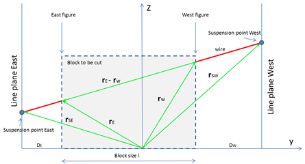
Transformation auf Bügel-Aufhängungskoordinaten
|
|
|
![]()
![]()
The
factors ![]() and
and ![]() are determined by an elementary way via
the simple intercept theorem:
are determined by an elementary way via
the simple intercept theorem:
![]() leads to
leads to ![]()
![]() leads to
leads to ![]()
This yields the transformation relation for the east and west suspension points of the bow:
![]()
![]()
The cutting data of the east and west figures (which are to be produced on the east and west sides of the block) must be transformed by these vector transformations to the respective bow suspension.
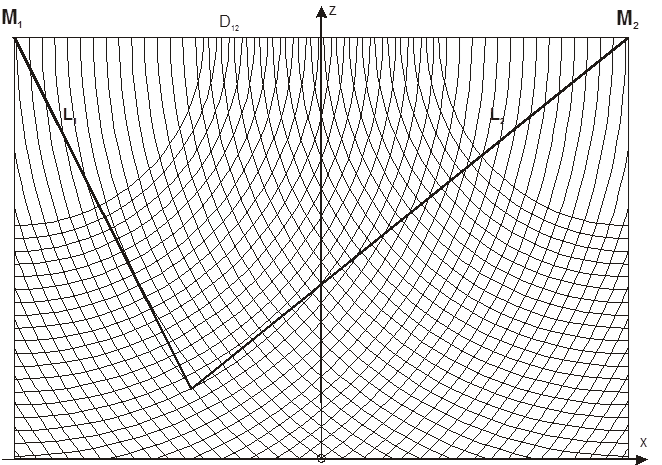
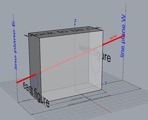
Comparison of the rope geometries
The left two geometries are mainly in use. The right implementation is only a slight variation of the second one. In the first variant the fishing lines L1 and L2 are directly drawn from the cutting wire to the motor shaft. The distance between the motor centers is D12.
The two left geometries are mainly used. The right realization is only a slight modification of the middle one. In the first variant, the cables L1 and L2 are guided directly from the cutting wire to the motor shaft. The motor centers have the distance D12 to each another. In the other variants, the rope is additionally deflected by small eyes, which are located under the respective other motor. In this case, the rope appears to come from a point, and with this assumption improves the accuracy of the coordinate transformation and thus the cutting results. But this is not quite true because an eye also has a finite extent (circa 3mm). This apparent advantage is bought with a strong rope load because the rope must be pulled over the small radius of curvature of the eyelet, resulting in not negligible friction and flattening as well as abrasion. If the eyelet becomes smaller, this effect is increased. In the last section, this influence is being discussed.
In addition, this cable guide variant works with more than twice the cable length, so that changes in the cable length due to the modulus of elasticity are noticeable and the accuracy is not just increased.
The direct variant is clearly preferable, especially since ICE in the current version correctly takes into account the finite geometry and, in addition, some important nonlinear effects. The rope is wrapped very gently. For deflections of x, z = 250mm one achieves accuracies of approx. 0.2mm. What more do you want!!
In this context, I have found a rope which can be considered a true super-rope and has proved itself excellently: diameter 0.3mm, material Coramid, extremely pre-stretched (Climax Protec red).
Author: H. Iwe
Date written: December 2010
Last modification: 12.12.2016